Hillink
Bridging the Geography Tax.
- Arquivos do projeto
- Documento final (LaTeX)
- Place from field research
- Vídeos
- Hillink: Cargo Transport on Steep Terrain
- Engineering Results and Limitations
- Practical Examples and Reference Capacity
Arquivos do projeto
Toos os arquivos do projeto. Mandem qualquer arquivo para joaaosc@proton.me que eu adiciono.
Abrir o índice de arquivos
| Categoria | Conteúdo |
|---|---|
| Todos os arquivos | renders, modelos, análises e vídeos |
| Modelo em AR | abre no iPhone e iPad |
| Modelo CAD | STEP, 13 MB |
| Lista de materiais | BOM em CSV |
| Artigo completo | PDF, 7,2 MB |
Pranchas técnicas
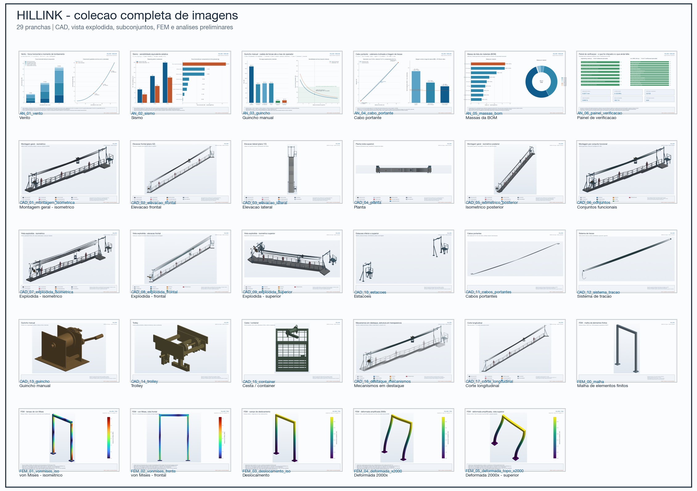
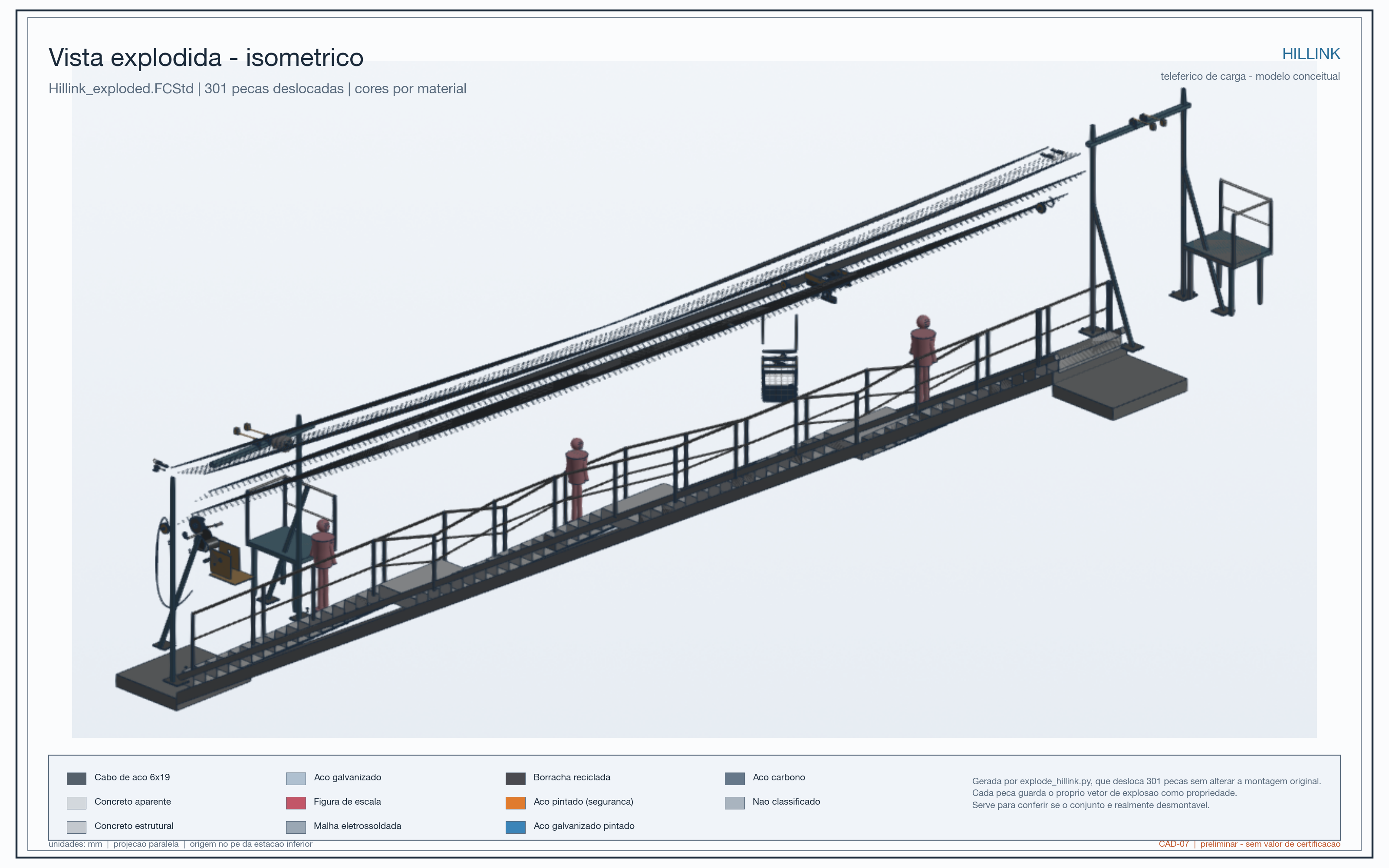
São 30 pranchas: 17 de CAD, 6 de FEM e 6 de análises.
Documento final (LaTeX)
Latest LaTeX compilation from the article if our proposal of the Hillink system.
PDF ·
Summary
São 31 sections, 16 figures and 22 tables. We only compiled and reviewd the document in English yet.
- Abstract
- Introduction
- What
- Why
- When
- Where
- Who
- Field Visit
- Past Solutions & Why They Failed
- Electric elevators
- Cable cars
- Our Solution: Hillink
- System Architecture: Spatial Separation and Clearance Requirements
- Structural and Mechanical Components
- Operational Safety and System Resilience
- Deployment Typologies and Terrain Adaptation
- Project Implementation
- Implementation Phases
- Costs, Maintenance & Financing
- Stakeholder Engagement and Financing Strategies
- Social Impact and Scalability
- Social Impact
- Scalability
- Limitations
- Conclusions
- References
- Appendix
Place from field research
Bridging the geography tax through community-driven mechanical infrastructure.
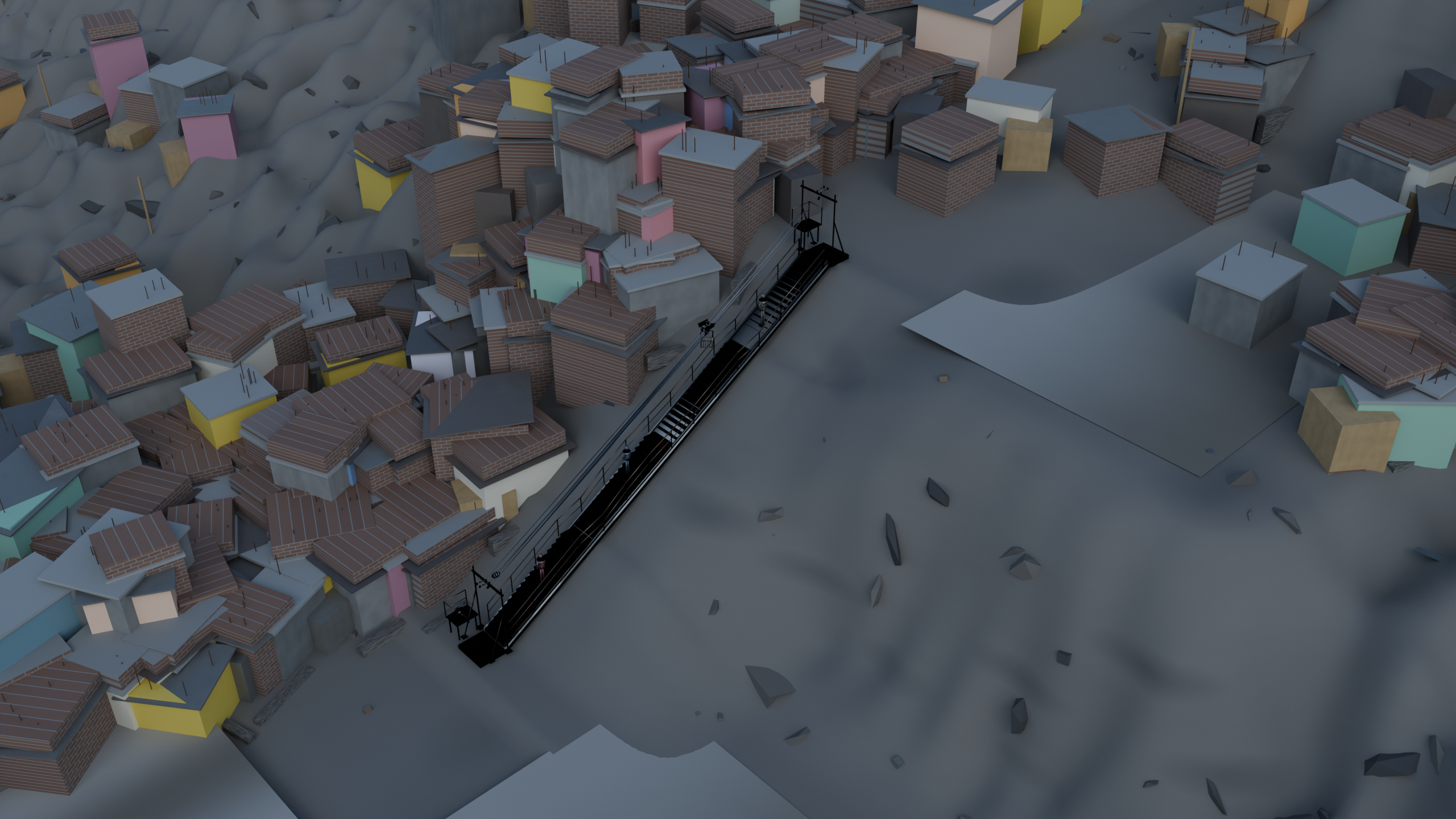
Local: Villa María del Triunfo, Lima — −12,15694, −76,93139
Vídeos
Vento
| Categoria | Valor |
|---|---|
| Vento — E.020 | 20,8 m/s, piso legal da norma |
| Sismo — E.030 | Zona 4 (Lima), solo S2 |
Hillink: Cargo Transport on Steep Terrain
Important notice: this page presents a concept and preliminary engineering results. Hillink is not a certified system, has not been released for fabrication, and must not be installed or operated without detailed design, site verification, authorization, and supervision by qualified professionals.

What is Hillink?
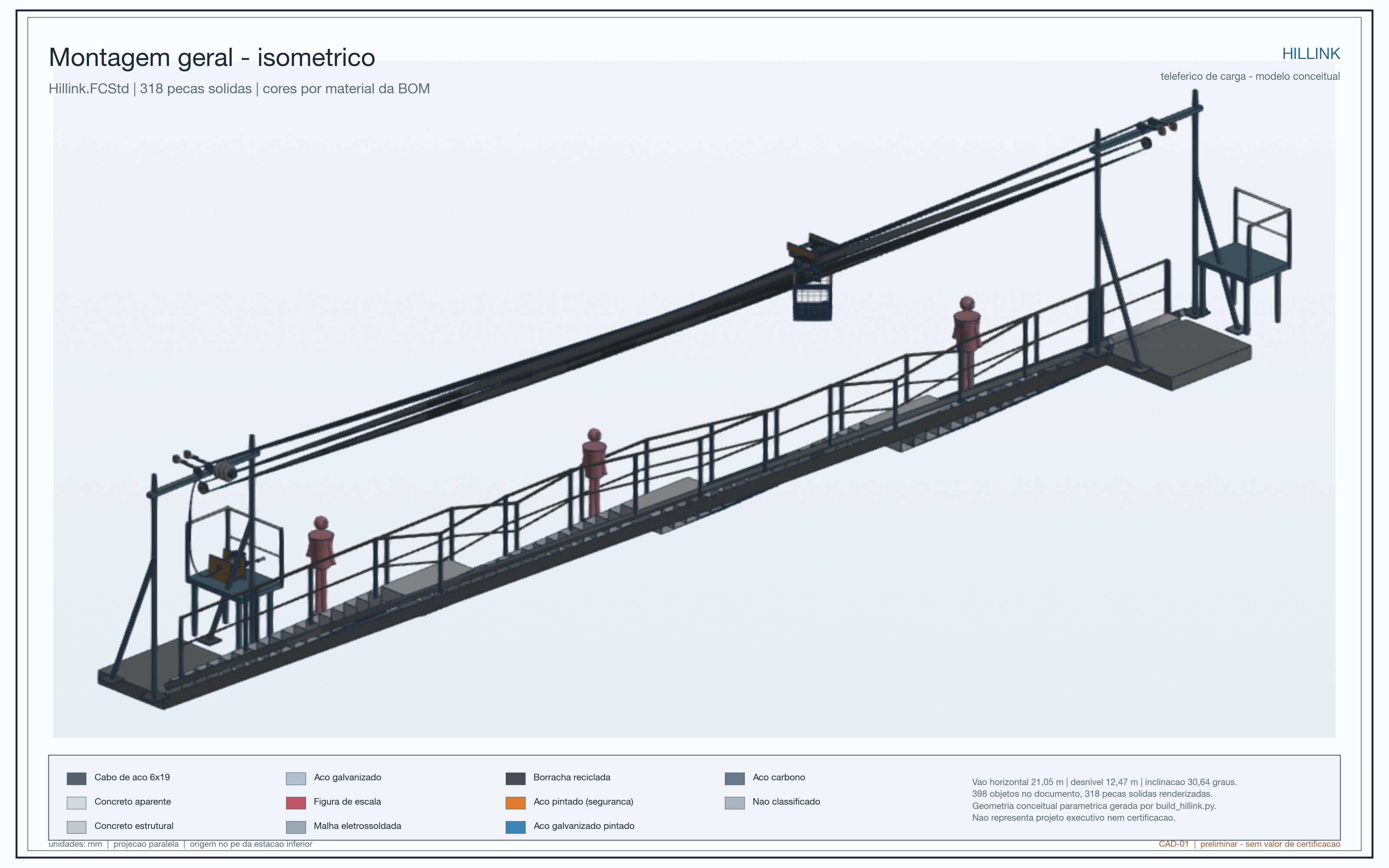
Hillink is a proposal for a mechanical cargo transport system for hillside communities where roads and vehicles cannot easily reach homes. The idea is to move essential goods along a steep route using a suspended trolley, cables, and a manual winch.
It is designed for cargo, not passengers: groceries, water, cooking gas, medicine, food, and small construction materials. The system does not depend on electricity and is arranged so that the stairway can remain available for pedestrians.
The project starts with a simple problem: when someone has to climb many stairs while carrying weight, the route costs more time, effort, money, and safety. The project calls this additional burden the Geography Tax.
How it would work
- The load is placed in a container at the lower station.
- A trolley with wheels travels along two carrier cables above the route.
- A separate haulage cable pulls the trolley.
- An operator turns a manual winch with a self-locking mechanism.
- At the upper station, the cargo is unloaded and the trolley can return.

The haulage cable is not the same cable that supports the load. This separation is one of the concept's safety ideas: if the pulling cable has a problem, the load remains supported by the carrier cables instead of depending on one line for both support and movement.
Scale of the studied model
Characteristic | Model value |
|---|---|
Horizontal span | 21.05 m |
Elevation gain | 12.47 m |
Inclination | 30.6° |
Carrier cables | 2 |
Nominal carrier cable diameter | 12.7 mm |
Empty container | 38.3 kg |
Reference contents | 46.1 kg |
Service weight of the moving assembly | about 1,489 N, equivalent to approximately 152 kg of mass, including trolley and cargo |
These values describe the analyzed model, not a universal Hillink capacity. A real installation would have to be recalculated for its terrain, length, supports, soil, wind, cable type, and actual load.
Why manual and non-electric?
The project was designed for places where an electric solution may be expensive, difficult to maintain, or dependent on an unstable grid. The manual winch reduces the number of electronic components and allows operation and maintenance to be learned locally.
This does not mean that the system is automatic or that it needs no rules. It would require trained operators, load limits, inspections, maintenance records, protection against misuse, and a clear stopping procedure.

Where could the idea make sense?
- steep stairways with little room for vehicles;
- hillside routes between a road-accessible point and a higher area;
- routes where pedestrian circulation must remain available;
- places where small loads are repeatedly carried by hand.
It is not automatically suitable for every hillside. A route may need to be rejected if it lacks reliable anchorage, has excessive wind exposure, is too narrow, creates conflicts with residents, or lacks local capacity to operate and maintain the equipment.
Social purpose and origin
The reference case was inspired by hillside communities in Villa María del Triunfo, Lima, Peru. Project interviews reported household loads of approximately 5 to 15 kg, trips of 10 to 20 minutes per direction, and particular difficulties for older residents, women, and caregivers.
Hillink is not intended to replace housing policy, roads, sanitation, or public transport. Its aim is narrower: to reduce the effort and cost of moving essential goods from the last accessible point to the home.
Current status
The current result is a detailed conceptual model with preliminary engineering screening. The project produced CAD drawings, mass estimates, wind and equivalent-seismic cases, a simplified cable analysis, a manual-winch force chain, and a simplified FEM submodel of the lower station.
The responsible next step would be to select a real route, survey it, confirm materials and anchorages, define operating rules, complete the structural design, and only then plan a controlled prototype or pilot.
Engineering Results and Limitations
Important notice: The numbers below are preliminary model results. They help explain the idea, compare scenarios, and identify what must be verified. They are not a manufacturing authorization, a safety certification, or a guaranteed capacity for any installation.
One-sentence summary
The study indicates that the concept may be mechanically plausible for a short span and a reference load, but it still depends on decisive checks of anchorages, foundations, real cables, fatigue, wind, seismic response, uncontrolled descent protection, and field operation.
What each analysis means
1. Mass and service load
The model uses an empty container of 38.3 kg and 46.1 kg of contents, for a total container load of about 84.4 kg. Including the trolley and hardware, the moving assembly considered in service weighs about 1,489 N, equivalent to roughly 152 kg of mass.
In simple terms: the studied case represents something like a heavy basket of groceries, water, or materials, not a passenger cabin. The very large mass that appears in the model inventory comes mainly from the floor and stair-support structure; that value must be confirmed on site because it strongly affects the seismic calculations.
2. Manual winch
For the 30.6° inclination, the model estimates:
Situation | Approximate hand force |
|---|---|
Continuous movement | 82 N, about 8.4 kgf |
Starting movement | 103 N, about 10.5 kgf |
This means that the operator would need to apply a force similar to pulling an 8 to 10 kgf load in the direction of the crank, under the assumed drum radius, reduction ratio, and efficiency. It is not a validated ergonomic measurement: real friction, wear, slope, wind, misalignment, and acceleration may increase the effort.

3. Carrier cables
In the simplified analytical check, each carrier cable reaches an approximate maximum tension of 9.85 kN in the scenario that includes the estimated trolley self-weight. Compared with the registered minimum breaking load of 87 kN per cable, this gives a ratio of approximately 8.8 to 1.
The correct interpretation is preliminary screening, not a final safety factor. The calculation does not adequately cover terminations, pulleys, repeated bending, fatigue, shock, wear, temperature, corrosion, real concentrated loads, or code-required factors. The 12.7 mm cable selection also came from a commercial reference and was not validated by a supplier or a test.

4. Wind
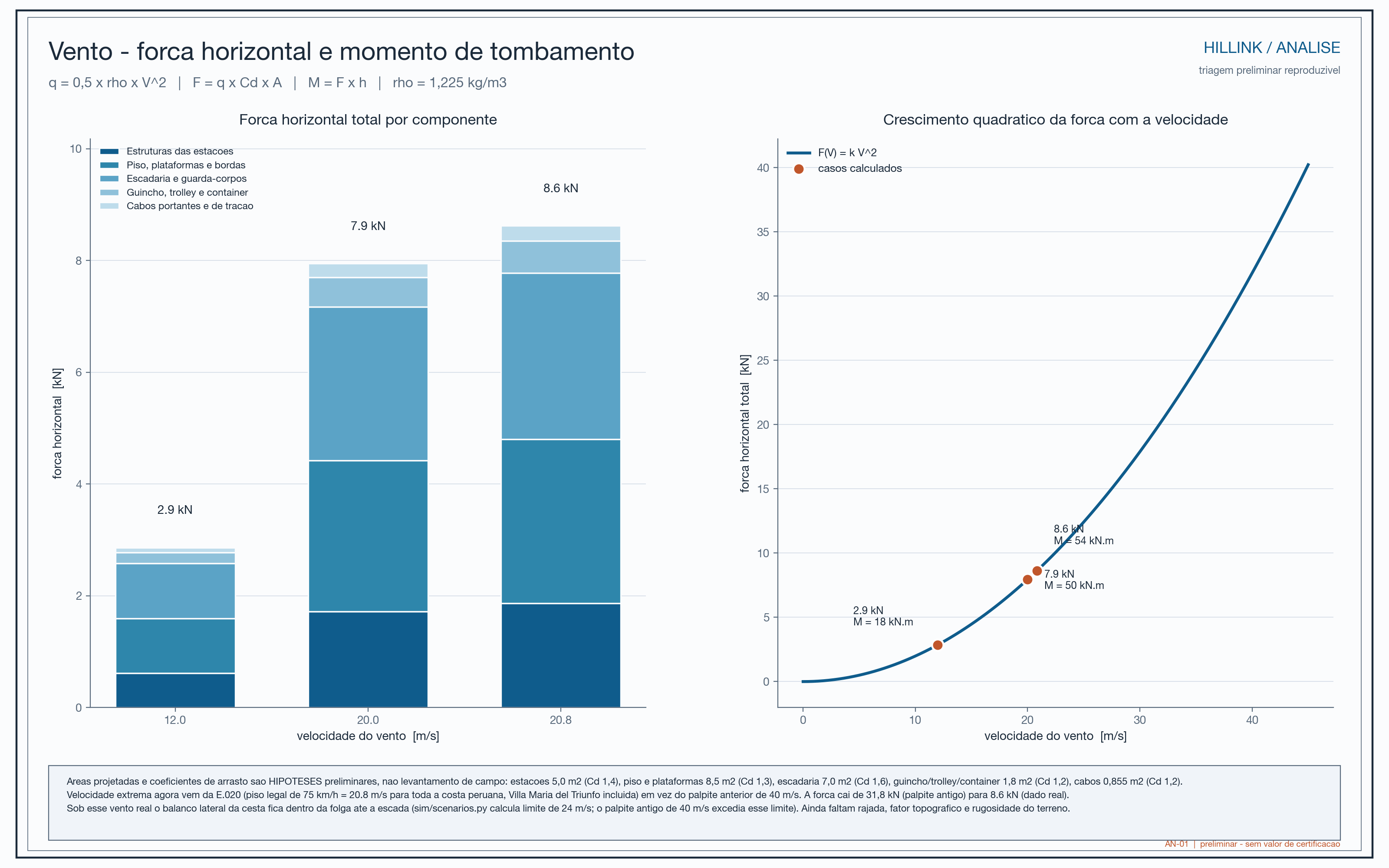
Because wind loading grows approximately with the square of wind speed, increasing the wind from 12 to 20 m/s does not increase the force by only a small amount: the calculated total force rises from about 2.9 kN to 7.9 kN. At 20.8 m/s, the screening case reaches 8.6 kN and about 54.2 kN·m of base moment.
These values use preliminary projected areas and drag coefficients. Real wind depends on gusts, height, structure shape, direction, topography, and route exposure. The suspended container may also swing.

5. Earthquake sensitivity
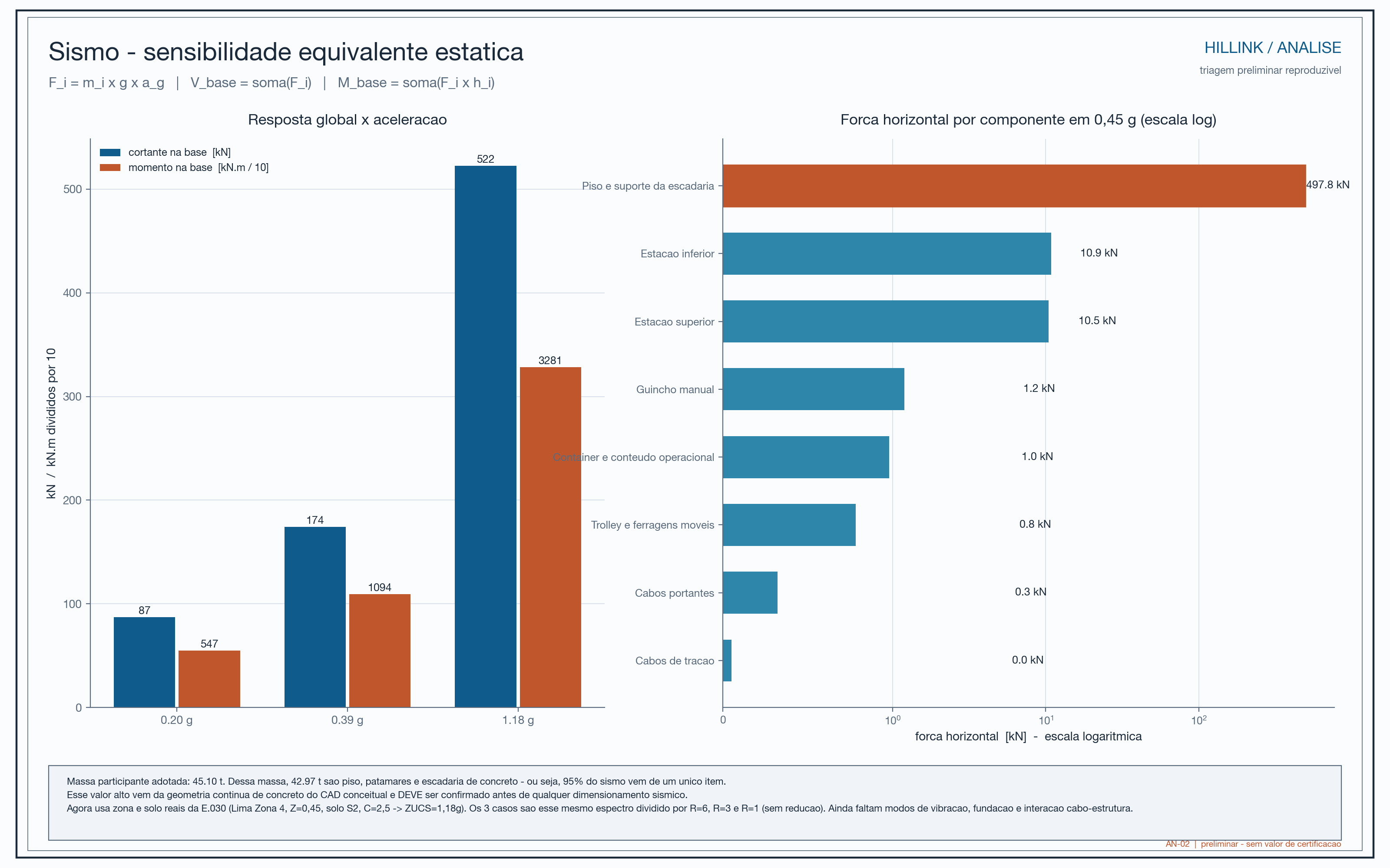
The seismic cases were equivalent-static sensitivity checks. They show how the forces could grow if a given acceleration were applied to the modeled mass:
Acceleration scenario | Calculated base shear | Calculated base moment |
|---|---|---|
0.20 g | 87.1 kN | 546.8 kN·m |
0.39 g | 174.1 kN | 1,093.6 kN·m |
1.18 g | 522.4 kN | 3,280.7 kN·m |
This is not a prediction of how Hillink would behave in an earthquake. It does not include vibration modes, a complete response spectrum, cable-structure interaction, ductility, soil, foundations, load combinations, or connection details. It indicates that the site and anchorages need serious study.

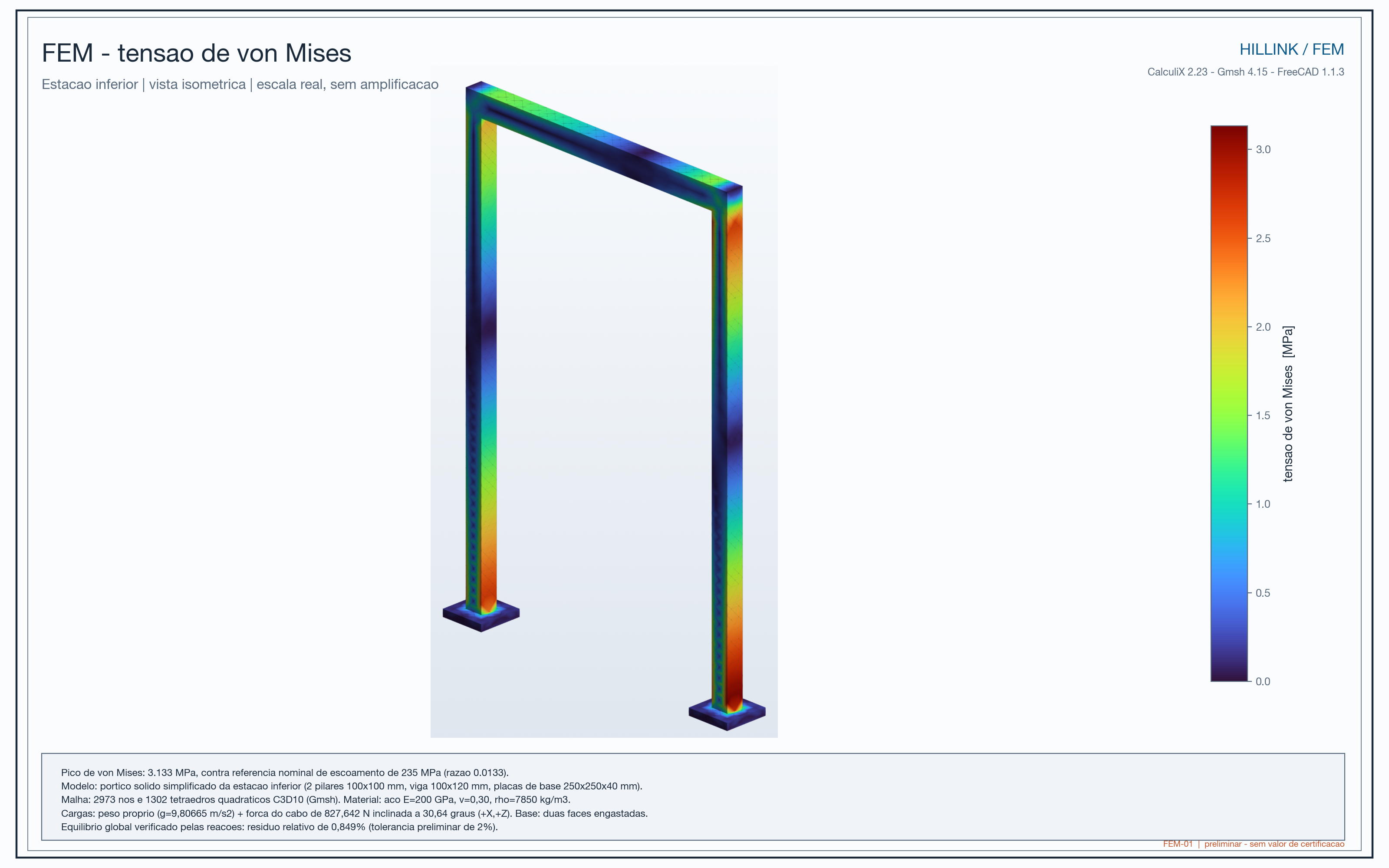
6. Lower-station FEM
A simplified solid submodel of the lower station, with ideally fixed bases, self-weight, and an 827.6 N operational load, returned:
- maximum displacement: 0.338 mm;
- maximum von Mises stress: 3.13 MPa;
- global equilibrium: passed within the recorded 2% tolerance.
In simple terms: within that simplified shape and those support conditions, the structure moved very little and the solver closed the example's equilibrium. This validates the calculation chain for the example, not the real station. The model does not reproduce actual tubes, welds, bolts, contact, foundations, anchorages, or mesh-convergence studies.


Limitations that change the interpretation
- The CAD is conceptual and does not replace fabrication drawings.
- Masses, material grades, and cable selection still need confirmation.
- The exact site, soil, foundation, and anchorage type are not defined with design data.
- Wind is a screening calculation using approximate areas and coefficients.
- Seismic loading is an equivalent-static sensitivity check, not a complete seismic analysis.
- The FEM analysis uses an idealized solid frame and does not represent all real joints and parts.
- Fatigue, corrosion, wear, inspection, transportation, assembly, and long-term maintenance were not validated.
- An uncontrolled trolley is still an independent safety problem: a haulage-cable break or ratchet failure can create meaningful speed and energy. Structural sizing alone does not solve that risk.
There is an important geometry issue: the cable-to-pulley diameter ratio appears as 15.75, while the adopted criterion indicated 18.We decided to raise the ratio- The estimated first natural frequency, 0.857 Hz, suggests sensitivity to gusts, but the mode may belong to the cable in the idealized topology and needs reassessment.
Possible improvements
- Replace assumptions with supplier data for materials, cables, pulleys, brakes, and anchorages.
- Design and test an independent uncontrolled-descent protection system.
- Analyze foundations, connections, welds, bolts, fatigue, corrosion, and impact.
- Redo wind and seismic analysis with site data and code load combinations.
- Study vertical clearance, container swing, and pedestrian interference.
- Establish load, speed, wind, and stopping limits.
- Test the winch with real loads and observe human effort over a complete cycle.
- Begin with an instrumented pilot and compare before-and-after measurements.
Practical Examples and Reference Capacity
How to read this page: The examples use the reference-case numbers to explain the concept. They must not be used on their own to decide what may be placed on a real installation.
Example 1: weekly groceries
Imagine a family buying 10 kg of food at the point where a motorcycle or vehicle can reach. Today, someone may have to carry those groceries up the stairs, possibly in more than one trip.
With Hillink, the load could be placed in the container at the lower station. The operator would close the container, operate the winch, and guide the trolley to the upper station. The person would still need to walk and carry the groceries for the final part, but would not need to carry the full weight across the entire steep route.
The model was studied with 46.1 kg of contents in addition to the 38.3 kg container. Therefore, 10 kg of groceries is below the reference load used in the simulation, but this does not mean that 10 kg is automatically approved: the real operating limit depends on testing, balance, container design, brake performance, wind, and local rules.

Example 2: cooking-gas cylinder
A gas cylinder is a useful example because it is heavy, bulky, and difficult to carry on a stairway. Hillink is intended to transport loads of this kind in a dedicated container, so that a person does not have to carry the cylinder on their body.
In practice, the cylinder would need to be secured so it could not tip or shift. The station would need to allow loading and unloading without lifting the object above waist height. The project would also need inspection rules, impact protection, container compatibility, and authorization from the responsible authorities.
The project did not demonstrate through testing that a gas cylinder can be transported safely. This example only shows why this type of load is part of the problem the system is intended to reduce.
Example 3: water and construction materials
A household may need to move water containers or small amounts of cement, timber, and tools. Instead of dividing the load among several people, the system could move one batch at a time.
The expected benefit is not to make the mountain disappear. It is to reduce the number of trips with weight, the time spent on the difficult segment, and physical exhaustion. To verify whether this actually happens, a pilot should record:
- how many manual trips were made before the pilot;
- how many kilograms were carried per week;
- how long each trip took;
- how much was paid for delivery or assistance;
- how many incidents, near-falls, or complaints occurred;
- how residents rated the effort before and after.
Example 4: what does 82 N mean?
The model estimates approximately 82 N of hand force during movement and 103 N at start-up. As a simple explanation, this is approximately equivalent to the weight-force of 8.4 kgf and 10.5 kgf.
This does not mean that the operator will hold exactly 8.4 kg in the air. The force depends on crank position and friction; it is only an approximate way to understand the calculated effort. An operator may be able to turn the crank but still become tired after many cycles. Ergonomics, rest periods, speed, and teamwork therefore need to be tested with real people.
Example 5: why wind matters so much
The preliminary calculation estimates about 2.9 kN of total force at 12 m/s and about 7.9 kN at 20 m/s. The difference is large because wind loading grows approximately with the square of wind speed.
As an analogy, pushing a door with a light breeze is different from pushing it with a strong gust. In Hillink, wind can push the structure, swing the container, change cable forces, and make the operator's work more difficult.
The real system would therefore need a wind limit, an anemometer or observation procedure, and a clear rule for stopping operation.
Example 6: why “the cable can take it” is not the end of the analysis
In the screening calculation, the maximum carrier-cable tension reached approximately 9.85 kN per cable, while the registered minimum breaking load was 87 kN per cable. The division gives approximately 8.8.
The correct reading is: in the simplified model, the calculated tension was below the registered breaking load. The incorrect reading would be: “the system is approved with a factor of 8.8.” Between those two statements are terminations, pulleys, bends, fatigue, corrosion, shock, installation, anchorages, and code requirements. Those details can change the result.
Example 7: what the FEM analysis actually showed
The FEM submodel represented a simplified lower station with two ideally fixed bases and an inclined operational load. The maximum result was 0.338 mm of displacement and 3.13 MPa of von Mises stress.
In educational terms: the idealized structure moved very little under that load. But this is like testing a structural model with perfect supports: it helps check the behavior of the example, but it does not guarantee that real soil, welds, bolts, and foundations will behave the same way.

What can Hillink carry according to the model?
The most honest formulation is:
The preliminary reference case was calculated for approximately 84.4 kg of cargo in the container, over a span of 21.05 m horizontally and 12.47 m of elevation gain, with an estimated hand force of 82 N during movement and 103 N at start-up. These values describe the studied case; they are not certified limits and cannot be transferred automatically to another route.
The model did not study passengers. It also does not authorize transporting hazardous, fragile, unstable, or larger loads without a specific design for them.
What responsible operation might look like
A pilot operation should work approximately as follows:
- An operator checks the cables, pulleys, container, brake, visible anchorages, and route.
- The load is weighed and kept below the approved limit for that pilot.
- The load is distributed and secured so it cannot tip.
- The stairway is cleared and people are warned during movement.
- The operator moves the trolley slowly, without sudden jerks.
- When the crank is released, the locking mechanism must prevent uncontrolled rollback.
- The load is unloaded at the station, and any noise, jamming, wear, or incident is recorded.
- The system is taken out of service if wind exceeds the limit, damage is found, or there is any doubt about safety.
This is a description of intended operation, not a ready-to-use manual. A real manual would need to be written and approved together with the design, tests, and local authorities.
What the pilot would need to prove
The pilot should not measure only whether the trolley moves. It should verify that the solution improves daily life without creating new risks:
- fewer manual trips;
- less transport time and cost;
- less weight carried on the body;
- lower exhaustion and dependence on assistance;
- no obstruction or conflict with pedestrians;
- reliable brake and uncontrolled-descent protection;
- stable container behavior with different loads;
- acceptable behavior in wind and rain within defined limits;
- maintenance that the community can actually perform.
In summary
Hillink is more like a small mechanical bridge for cargo than a passenger cable car. The concept makes sense when the main problem is the last segment between the road and the home. It may reduce human effort, but it will be a real solution only if the route is suitable, anchorages are verified, limits are respected, and the community can operate and maintain the system.